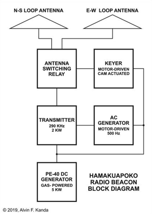
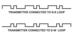
the E-W loop. Note that when either loop was activated, the other was not. When the aircraft was where the signal strength from the two antennas were equal, the A's and N's merged to form a continous signal. The dashes and dots were formed by a switch activated by a motor-driven cam.
The transmitter was an obsolete 5-Kw spark type converted to vacuum tubes (pair of UV-851's). The tubes received their 500 Hz ac plate voltage via opposite legs of a center-tapped transformer. When one tube was operational the other tube was inactive (vacuum tubes operate only with a positve plate voltage). The result was that the 290 KHz radio frequency was produced on each half cycle of the 500 Hz plate supply. The transmitter output can be described as a 290 KHz carrier amplitude modulated with a predominately 1000 Hz tone.
The Signal Corps PE-40 was a 5 Kw dc generator powered by a water-cooled, 4 cylinder gasoline engine. It powered the transmitter tube filaments, 500 Hz generator, keyer motor, antenna switching relay as well as the shack lighting.
References
- Shangraw, C. C. " Radio Beacons for Transpacific Flights". Proc. Inst. Radio Eng., vol. 16 (1928): 1203ñ1235
Beacon Background Information
Beacon Chronology
|